
This article provides you with all the necessary information on the installation process. It consists of a V-shaped structure that supports two main cameras plates, two optional column cameras, a computer with screen, a PoE switch, and other essential components.
The V-shaped structure weighs approximately 120 kg (265 lbs).
 Part List Truss Construction
| 2x | F33150 (1.5 m) | 
|
| 2x | F33200 (2.0 m) | 
|
| 2x | F33100 (1.0 m) | 
|
| 2x | FF33125 (1.25m) | |
| 2x | F33T36 (T-shaped) | 
|
| 1x | F33C24 (90° angle) | 
|
| 2x | F33BASEBE (base plate) | 
|
Part List MetriXFreight Components
| 2x | MetriXFreight L23x main camera plate |  |
| 1x | MetriXFreight computer on plate with mounting clamps |  |
| 1x | MetriXFreight PoE Switch on plate with mounting clamps | |
| 3x | Ethernet cable medium (3m, for close camera plate to switch and PC to switch) | |
| 2x | Ethernet cable long (5m - 7.5m) If there are two additional column cameras, then there will be four long cables.) | |
| 1x | Wireless keyboard | |
| 1x | Screen | |
| 1x | Multi-Socket for power supply | |
| Optional: NSP Add-on, consisting of 3 additional cameras |
There are two variations available for the camera plate - one with a color camera attached to the 3D camera and the other without.
Before you start
It is recommended to begin with the installation of the upper part of the system and complete all wiring for the cables. This approach eliminates the need for working at heights towards the end of the installation process. After connecting the upper parts of the system, it can be lifted onto the columns using a forklift. Then, the columns need to be securely fastened to the ground in the final position of the structure.
Determine the placement of your screen, choosing either the left or right column. This decision will dictate the location of the PC, which should be positioned on the same side as the selected screen. In our example below we decided to use the right column.
The installation follows a logical sequence.

Step 1: Building the Top Structure
Begin by connecting one F33125 (1.25m) with a F33T36 (T-shaped), and then add another F33100 (1m).
Next, add the F33C24 corner.
Add another F33100 (1m) on the opposite side of the corner, followed by a F33T36 (T-shaped) and the last F33125 (1.25m) part.
Using a hammer, securely fasten the pins to connect the truss elements. It is important to ensure that each pin is properly secured with a clip.
As the final step, securely install the two pre-mounted SmartEye plates onto the outer sides of the structure using the attached clamps. The plates need to be secured as far out on the structure as possible.
After completing all the steps, your structure should look exactly like the provided image.

Step 2: Attach Cables and Columns
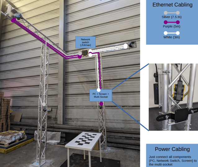
At this point it is recommended to connect the ethernet cables to the PoE Splitter(s) and, if applicable, the color cameras. Check that the two very short cables between the PoE splitters and the (blue) range cameras are attached properly.
Guide the cables inside the truss and connect them to the PoE network switch (label "Edimax"), which should be mounted next to the T-Piece of the column where the screen will be attached. The ethernet connection cable for the PC can be connected to the network switch as well during this step.
In case of additional color cameras on the truss columns, please already guide the corresponding cables through the upper part of the truss.
Here is a schematic view on how the cabling should look like in the end:
Next, rotate the structure by 90 degrees and securely attach the F33200 (2m) element to the F33T36 (T-shaped) using the provided pins and clips.
Using a hammer, securely fasten the pins to connect the truss elements. It is important to ensure that each pin is properly secured with a clip.
Once the previous step is complete, it is recommended to rotate the structure again and proceed with the installation of the second F33200 (2m) component in the same manner as before.
Now, utilize the column that you have identified as the screen column to carefully thread the Ethernet cables through the F33200 (2m) component and securely attach them in place.
Ensure that you do not excessively pull on the plugs and electrical devices when fastening the cables.
Once this is complete, rotate the structure back to its original position.
Step 3: Finalize the Structure
To determine the correct position of the system without having to move the entire setup, we employ a helpful technique. We will identify the optimal placement of the base plates at this stage:
Carry the complete upper section (with the 2m columns) to the target position and place it on the base plates. Then screw the base plates into the ground using the provided bolt anchors.
Now that the base plates are securely anchored, the final two truss elements can be inserted into the system.
Lift the pre-assembled structure (without base plates) using a forklift. To further stabilize the lifting process, a 3 m or longer plank can be used to grip the structure under the t-pieces (the tip of the forks are underneath the corner of the structure then).
During this action, each column should be held by at least by two people. Then insert the 1.5m truss elements to reach the target height.

Using a hammer, securely fasten the pins to connect the truss elements. It is important to ensure that each pin is properly secured with a clip.
Once in place, firmly secure all components with pins and clips using a hammer. As long as not all pins and clips are fixed, the structure must still be secured against tipping over by the forklift and people at the columns.
Floor anchors are absolutely essential for every installation!
Click here for more information on floor anchors.
We recommend installing a protective barrier around the system to prevent any accidental damage.
If V-shape is used with a scale
This is how the scale (dark grey) is supposed to be positioned.
scale - dark grey
V-shape - light grey
measurement area - green
The V-shaped structure can be positioned at any corner as needed.


Step 4: Mount Additional Equipment
Screen Mounting
You will find instructions to prepare and mount the screen here: Screen Mounting
Barcode Scanner
Just connect the barcode scanner to the PC and fix the base station within the truss components.